Electro Mechanical Cylinders
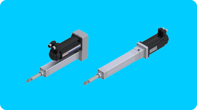
Linear actuators, also called electro-mechanical cylinders (EMC's) offer numerous advantages over, for example, a hydraulic cylinder. An EMC has higher dynamics and precision, better controllability, and greater mechanical efficiency. In order to achieve the best configuration for your application, the 6 input parameters below must be met. In step 7 you put these parameters into our product configurator.
Step 1; The load
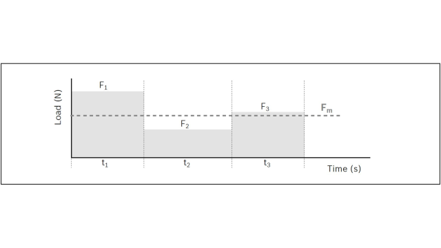
Only if the loads (process forces and masses) have been accurately mapped can an EMC be chosen that is both economical and reliable. In addition to the maximum force in the application, it is important to also indicate changing forces over the stroke so that the average load over the entire cycle can be determined. A distinction must also be made between the static and the dynamic load.
Step 2; The duty cycle
The duty cycle is the ratio between operating time and total cycle time. This is an important parameter to be able to estimate the total life of the cylinder as well as for the thermal determination of cylinder and engine. Dwell times should always be included in the calculation.
Step 3; The total cycle
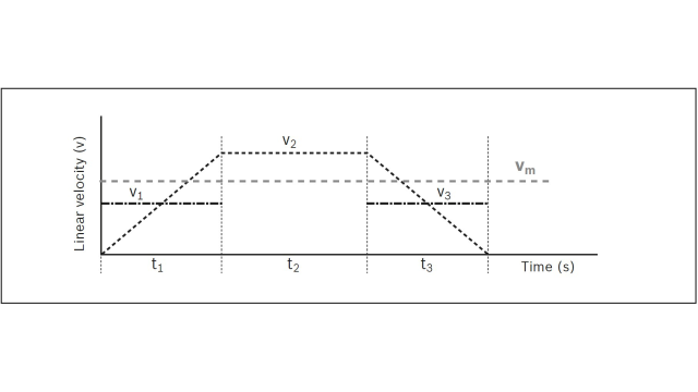
The more accurate the acceleration, linear speeds, required cycle time and the stroke length are entered into the configurator, the better the driveline fits your application. It is therefore important to map this out properly.
Step 4; The integration in the machine
Lateral forces and misalignments during installation can drastically shorten the life of the EMC. During assembly, care must be taken to ensure that the cylinder is installed free of deforming stresses, and heavy lateral loads are absorbed by an external conductor. Also, the type of attachment and the EMC fastening element affect the maximum permissible axial load.
Step 5; The stroke length and dimensions
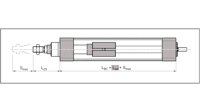
Determine the required stroke in your application. Please note that EMC's should not move to the mechanical end stop. Therefore, it is important to add extra stroke to both ends of the effective control stroke. This maximum range of motion (smax) is the parameter to be entered in the configurator. For construction reasons, the total length of the cylinder exceeds the maximum range of motion (smax).
Need help with steps 1 through 5? Then use LinSelect, this eTool will guide you through the entire process without any problems.
Step 6; The environmental condition
The environment in which a cylinder is used can have a significant impact on its service life. Both very high and very low temperatures can affect the seals, lubrication and performance of the engine. Abrasive dirt and chemicals can damage the seals and ultimately cause the spindle drive to fail in the long run. Ask yourself if there are any circumstances that need to be taken into account.
Step 7; The configurator
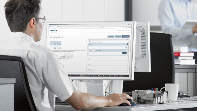
Now that you have thought about everything, and it has all been mapped out, configuring the EMC in our online configurator is easy. This will help you step by step through the whole process. From this configurator roll both CAD files (2D and 3D) and the order code.

