Cancel
好的
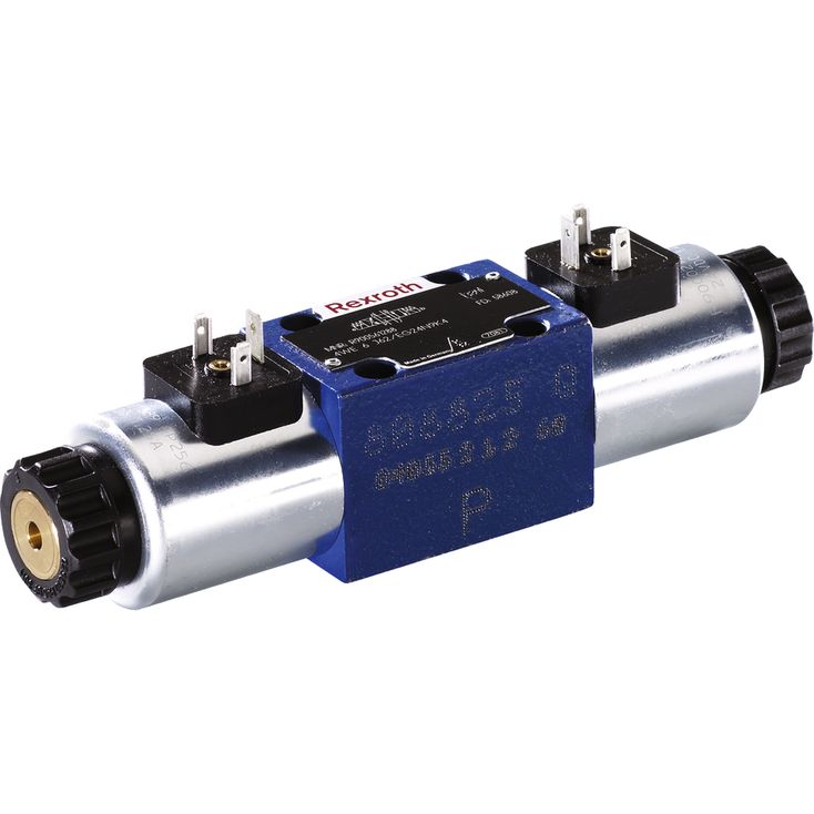
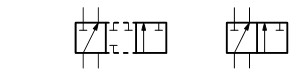
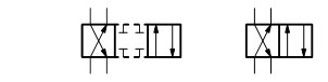
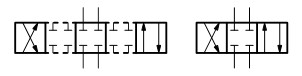
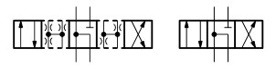
Directional spool valves, direct operated, with solenoid actuation – Type WE 6...E
咨询留言
产品型号
WE
6
6X
/
E
Result count
3383 的 3383
Main ports
3
3 main ports
4
4 main ports
Type
Directional valve
WE
Directional valve
Size
Size 6
6
Size 6
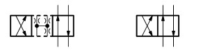
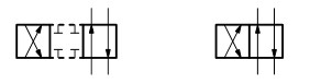
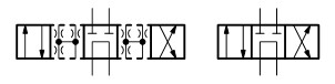
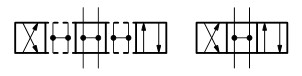
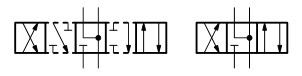
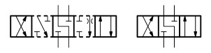
Symbol
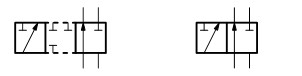
A
C
D
B
Y
E
F
G
H
J
L
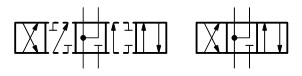
M
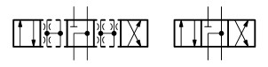
P
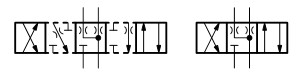
Q
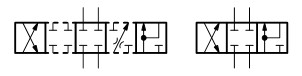
R
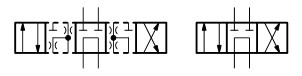
T
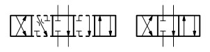
U
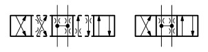
V

W
Series
Series 60 … 69
6X
Series 60 … 69
Spring return / detent
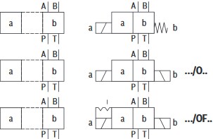
With spring return
O
Without spring return
OF
Without spring return with detent
Solenoid version
High-power solenoid, wet-pin, with detachable coil
E
High-power solenoid, wet-pin, with detachable coil
Solenoid voltage
G110
Direct voltage 110 V
G12
Direct voltage 12 V
G125
Direct voltage 125 V
G180
Direct voltage 180 V
G205
Direct voltage 205 V
G220
Direct voltage 220 V
G24
Direct voltage 24 V
G26
Direct voltage 26 V
G48
Direct voltage 48 V
G96
Direct voltage 96 V
W100
AC voltage 100 V 50/60 Hz
W110
AC voltage 110 V 50/60 Hz
W120
AC voltage 120 V 50/60 Hz
W200
AC voltage 200 V 50 Hz
W230
AC voltage 230 V 50/60 Hz
Manual override
Without manual override
N
With manual override
N2
With manual override "mushroom button" (small)
N4
With lockable manual override "mushroom button" (small)
N5
With lockable manual override "mushroom button" (large)
N6
With manual override "mushroom button" (large), not lockable
N7
With lockable manual override "nut"
N9
With concealed manual override (standard)
Corrosion resistance
None (valve housing primed)
J3
Improved corrosion protection (240 h salt spray test according to EN ISO 9227
J5
High corrosion protection (720 h salt spray test according to EN ISO 9227)
Electrical connection
K4
Connector 3-pole (2 + PE) according to DIN EN 175301-803 (Standard)
K4K
Connector 3-pole (2 + PE) according to DIN EN 175301-803 With potted-in plug base and sealing element
K40
Connector 2-pole, DT04-2PA (Deutsch type)
K72L
Connector, 4-pole, M12x1 according to DIN EN 61076-2-101 with suppressor diode, coding A
K73L
Connector, 4-pole, M12x1 according to DIN EN 61076-2-101 with suppressor diode, coding A (Standard)
C4
Connector 2-pole (Junior-Timer type)
Spool position monitoring
Without position switch
QMAG24
Inductive position switch type QM: Monitored spool position „a″
QMBG24
Inductive position switch type QM: Monitored spool position „b″
QR0G24S
Inductive position switch type QR: Monitored rest position
QRABG24E
Inductive position switch type QR: Monitored spool position "a" and "b"
QSAG24W
Inductive position switch type QS: Monitored spool position „a″
QSBG24W
Inductive position switch type QS: Monitored spool position „b″
QS0G24W
Inductive position switch type QS: Monitored spool position „0“
QSABG24W
Inductive position switch type QS: Monitored spool position „a“ and „b“
Additional options
Without additional options
/
With additional options
Switching time increase
Without switching time increase
A12
With switching time increase
Throttle insert port A
Without throttle insert
H08
Throttle Ø 0,8 mm [0.031 inch]
H10
Throttle Ø 1,0 mm [0.039 inch]
H12
Throttle Ø 1,2 mm [0.047 inch]
H15
Throttle Ø 1,5 mm [0.059 inch]
H20
Throttle Ø 2,0 mm [0.079 inch]
H25
Throttle Ø 2,5 mm [0.098 inch]
Throttle insert port B
Without throttle insert
R06
Throttle Ø 0,6 mm [0.024 inch]
R08
Throttle Ø 0,8 mm [0.031 inch]
R10
Throttle Ø 1,0 mm [0.039 inch]
R12
Throttle Ø 1,2 mm [0.047 inch]
R15
Throttle Ø 1,5 mm [0.059 inch]
R20
Throttle Ø 2,0 mm [0.079 inch]
R25
Throttle Ø 2,5 mm [0.098 inch]
R30
Throttle Ø 3,0 mm [0.120 inch]
R40
Throttle Ø 4,0 mm [0.160 inch]
Throttle insert port A and B
Without throttle insert
N06
Throttle Ø 0,6 mm [0.024 inch]
N08
Throttle Ø 0,8 mm [0.031 inch]
N10
Throttle Ø 1,0 mm [0.039 inch]
N12
Throttle Ø 1,2 mm [0.047 inch]
N15
Throttle Ø 1,5 mm [0.059 inch]
N20
Throttle Ø 2,0 mm [0.079 inch]
N30
Throttle Ø 3,0 mm [0.120 inch]
Throttle insert port T
Without throttle insert
X06
Throttle Ø 0,6 mm [0.024 inch]
X08
Throttle Ø 0,8 mm [0.031 inch]
X10
Throttle Ø 1,0 mm [0.039 inch]
X12
Throttle Ø 1,2 mm [0.047 inch]
X15
Throttle Ø 1,5 mm [0.059 inch]
X20
Throttle Ø 2,0 mm [0.079 inch]
X30
Throttle Ø 3,0 mm [0.120 inch]
X40
Throttle Ø 4,0 mm [0.160 inch]
Clamping length
42 mm [1.65 inch] (Standard)
Z
22 mm [0.87 inch]
Control spool play
Standard (recommended)
T06
Minimum
T12
Increased
Seal material
NBR seals
V
FKM seals
MH
Recommended for operation with HFC hydraulic fluids together with high temperatures
MT
Low-temperature version
Approval
Standard
=UR
Solenoid coil as approved component with UR marking according to UL 906, edition 1982
=CSA
Approval according to CSA C22.2 No. 139-1982
=AN
Porting pattern according to ANSI B93.9
Locating hole
Without locating hole
/62
With locating hole and locking pin ISO 8752-3x8-St
Electric power consumption
Standard
SO407
With reduced electric power consumption
Additional details
-86
-86
-87
-87
/60
/60
/60SO407
/60SO407
/Z=ANSO43A-1799A
/Z
+BOLTSM5X50
+BOLTSM5X50
+G342
+G342
+PLUGINCONNECTOR
+PLUGINCONNECTOR
=AN
AN
=CSA
CSA
=KM
KM
=PL
PL
=SH
SH
03
03
03/B08
03/B08
03/MT
03/MT
6
6
6/V
6/V
6/VSO9
6/VSO9
6/ZV
6/ZV
60
60
62
62
62=AN
62
62=CSA
62
62=UR
62
62SO21
62SO21
62SO407
62SO407
62SO407=AN
62SO407
62SO43A-1018
62SO43A-1018
62SO43A-1042
62SO43A-1042
62SO43A-1096
62SO43A-1096
62SO43A-1338
62SO43A-1338
62SO43A-1461
62SO43A-1461
62SO43A-1654
62SO43A-1654
62SO43A-1723
62SO43A-1723
62SO43A-1773
62SO43A-1773
62SO43A-1777
62SO43A-1777
62SO43A-1797
62SO43A-1797
62SO43A-1799
62SO43A-1799
62SO43A-1799A
62SO43A-1799A
62SO43A-1809
62SO43A-1809
62SO43A-1855
62SO43A-1855
62SO43A-686-1
62SO43A-686-1
62SO859
62SO859
62SO888
62SO888
62SO9
62SO9
62SO99
62SO99
B00
B00
B05
B05
B05SO526
B05SO526
B07
B07
B14=CSA
B14
B14=CSA=AN
B14
B16
B16
B16=AN
B16
B16=CSA
B16
B16=CSA=AN
B16
B16SO43A-1799A
B16SO43A-1799A
B18
B18
B18=UR
B18
B18MH
B18MH
B18SO407
B18SO407
B18SO43A-1799+1833CAT
B18SO43A-1799+1833CAT
B18SO899
B18SO899
B18V
B18V
B22
B22
B24SO43A-1799+1833CAT
B24SO43A-1799+1833CAT
B28
B28
B28V
B28V
B35
B35
H00
H00
H00SO407
H00SO407
H05
H05
H18
H18
H22
H22
JLG
JLG
ML
ML
N05
N05
N14
N14
N18
N18
N28
N28
N28V
N28V
QLAG24/B12
QLAG24/B12
QRAG24S
QRAG24S
QRBG24S/ZV
QRBG24S/ZV
QYAG24
QYAG24
QYBG24
QYBG24
QYBG24=HT
QYBG24
R00/62
R00/62
R04
R04
R04SO407
R04SO407
R22
R22
R22V
R22V
R35
R35
S043A-1799
S043A-1799
SO194
SO194
SO21
SO21
SO256
SO256
SO258
SO258
SO292
SO292
SO293
SO293
SO343
SO343
SO43A-1042
SO43A-1042
SO43A-1096
SO43A-1096
SO43A-1221-A
SO43A-1221-A
SO43A-1338
SO43A-1338
SO43A-1338JLG
SO43A-1338JLG
SO43A-1743
SO43A-1743
SO43A-1777
SO43A-1777
SO43A-1799
SO43A-1799
SO43A-1799+1833
SO43A-1799+1833
SO43A-1799+1833CAT
SO43A-1799+1833CAT
SO43A-1799A
SO43A-1799A
SO43A-1809
SO43A-1809
SO43A-1820A
SO43A-1820A
SO43A-1820B+1338
SO43A-1820B+1338
SO43A-1820C+1338
SO43A-1820C+1338
SO43A-1822
SO43A-1822
SO43A-1833
SO43A-1833
SO43A-1852
SO43A-1852
SO43A-1860
SO43A-1860
SO43A-1870
SO43A-1870
SO43A-1871
SO43A-1871
SO43A-1872
SO43A-1872
SO43A-1872-A
SO43A-1872-A
SO43A-1872-A=AN
SO43A-1872-A
SO43A-1872=AN
SO43A-1872
SO43A-686-1
SO43A-686-1
SO43A-978-1
SO43A-978-1
SO43A1799-1839
SO43A1799-1839
SO43A686-1
SO43A686-1
SO461
SO461
SO523
SO523
SO524
SO524
SO525
SO525
SO529
SO529
SO530
SO530
SO531
SO531
SO533
SO533
SO534
SO534
SO561
SO561
SO617
SO617
SO680
SO680
SO692
SO692
SO694
SO694
SO722
SO722
SO778
SO778
SO797
SO797
SO806
SO806
SO810
SO810
SO811
SO811
SO828
SO828
SO829
SO829
SO851
SO851
SO855
SO855
SO859
SO859
SO859SO43A-1741
SO859SO43A-1741
SO871
SO871
SO880
SO880
SO887
SO887
SO888
SO888
SO889
SO889
SO895
SO895
SO896
SO896
SO898
SO898
SO9
SO9
SO9=AN
SO9
SO9=CSA
SO9
SO9=UR
SO9
SO907
SO907
SO931
SO931
SO941
SO941
SO942
SO942
SO951
SO951
SO956
SO956
SO99
SO99
SO99=CSA
SO99
SO9JLG
SO9JLG
X04/62
X04/62
X18
X18
X27/62
X27/62
X28V
X28V
ZV
ZV
说明文档
Add to basket
| You have successfully finished your selection. |
| 物料代码: |
Product description
产品型号:WE66X/E
| The following data were selected. | ||
|---|---|---|
| Type | WE | Directional valve |
| Size | 6 | Size 6 |
| Series | 6X | Series 60 … 69 |
| Solenoid version | E | High-power solenoid, wet-pin, with detachable coil |