Cancel
OK
ColombiaEspañol
Seleccione su localización
Industrias
Vista general- Agricultura y Forestal
- Industria de la Automoción
- Producción de baterías
- Industria química
- Construcción e infraestructura
- Bienes de consumo
- Energía y servicios
- Cuidado de la Salud
- Hidrógeno
- Logística y transporte
- Materiales y recursos
- Metalurgia
- Industria farmacéutica
- Reciclaje y manejo de residuos
- Energías renovables
- Semiconductores y Electrónica
- Tecnología de pruebas
- Automatización de almacén y logística interna
Servicio y soporte
Vista generalDescargas
Vista generalCarreras
Vista generalCompañia
Vista generalSoluciones industriales
Vista general- Tecnología de montaje
- Controles y Accionamientos eléctricos
- Hidráulica industrial
- Tecnología de movimiento lineal
- Tecnologías de moldeo y fundición
- Tecnología de atornillado
- Soldadura por Resistencia
- Sistemas de movimiento y transporte
- Robótica móvil
- Soluciones de accionamiento Hägglunds
- Kassow Robots
- Catálogo de aplicaciones
Soluciones para máquinas móviles
Vista generalAutomatización de almacén y logística interna
Vista generalServicio
Vista generaleConfigurators y herramientas online
Vista generalAutomation Community
Vista generalEducación y formación para las industrias
Vista generalRed de socios comerciales
Vista generalInternational
Cierre de sesión
Seleccione su localización
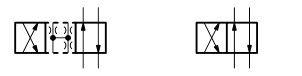
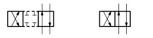
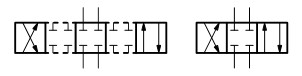
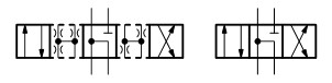
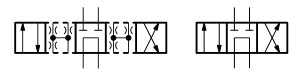
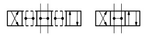
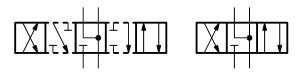
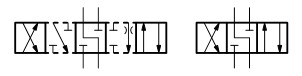
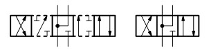
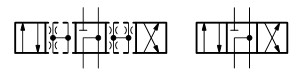
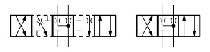
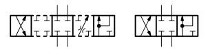
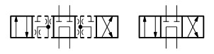
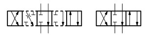
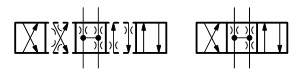
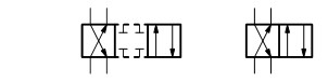
Directional spool valves, direct operated, with solenoid actuation WE 10…E
Consulta de asesoramiento
Código
WE
10
5X
/
E
/
Result count
1010 de 1010
Main ports
3
3 main ports
4
4 main ports
Type
Directional valve
WE
Directional valve
Size
Size 10
10
Size 10
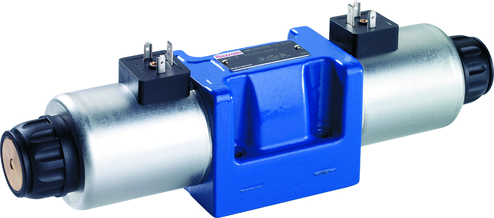
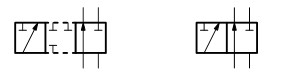
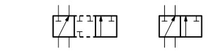
Symbol
A
B
C
D
E
F
G
H
J
L
M
P
Q
R
T
U
V

W
Y
Series
Series 50 … 59
5X
Series 50 … 59
Spring return / detent
With spring return
D
With reinforced compression spring
O
Without spring return
OF
Without spring return with detent
Solenoid version
High-power solenoid, wet-pin, with detachable coil
E
High-power solenoid, wet-pin, with detachable coil
Solenoid voltage
G110
Direct voltage 110 V
G12
Direct voltage 12 V
G125
Direct voltage 125 V
G180
Direct voltage 180 V
G205
Direct voltage 205 V
G220
Direct voltage 220 V
G24
Direct voltage 24 V
G26
Direct voltage 26 V
G48
Direct voltage 48 V
G96
Direct voltage 96 V
W100R
AC voltage 100 V
W110R
AC voltage 110 V
W120R
AC voltage 120 V
W200R
AC voltage 200 V
W230R
AC voltage 230 V
Manual override
Without manual override
N5
With lockable manual override "mushroom button" (large)
N6
With manual override "mushroom button" (large), not lockable
N8
With concealed manual override and protective cap
N9
With concealed manual override (standard)
Corrosion resistance
None (valve housing primed)
J3
Improved corrosion protection
Electrical connection
C4Z
Individual connection without mating connector; connector AMP Junior-Timer
DAL
Central connection, without mating connector; threaded connection 1/2"-14 NPT
DJL
Central connection, cable gland at the cover, with indicator light and cable bridge at the ground connection
DK25L
Central connection, mini-change connector, 5-pole
DK6L
Central connection, central plug-in connection at the cover, with indicator light (without mating connector)
DL
Central connection, cable entry at the cover, with indicator light
K4
Individual connection without mating connector; connector according to DIN EN 175301-803
K4K
Individual connection without mating connector; connector according to DIN EN 175301-803 (coil and sealing element included)
K72L
Individual connection without mating connector, 4-pole with connector M12x1 according to IEC 60947-5-2
Additional options
With additional options
/
With additional options
Switching time increase
Without switching time increase
A12
With switching time increase
Use with flows which exceed the performance limit of the valve (see Product description).
Without throttle insert
B00
B00
B04
B04
B08
Throttle Ø 0.8 mm
B10
Throttle Ø 1.0 mm
B12
Throttle Ø 1.2 mm
B15
B15
B20
B20
B25
B25
B30
B30
B35
B35
B40
B40
Use with flows which exceed the performance limit of the valve (see Product description).
Without throttle insert
H08
Throttle Ø 0.8 mm
H10
Throttle Ø 1.0 mm
H12
Throttle Ø 1.2 mm
H20
H20
H30
H30
Use with flows which exceed the performance limit of the valve (see Product description).
Without throttle insert
R08
Throttle Ø 0.8 mm
R30
R30
Use with flows which exceed the performance limit of the valve (see Product description).
Without throttle insert
N10
Throttle Ø 1.0 mm
Use with flows which exceed the performance limit of the valve (see Product description).
Without throttle insert
X08
Throttle Ø 0.8 mm
X10
Throttle Ø 1.0 mm
X12
Throttle Ø 1.2 mm
X20
X20
X40
X40
X70
X70
Control spool play
Standard
T06
Minimum (to be selected in case of reduced leakage → higher level of oil cleanliness recommended)
T12
Increased (to be selected in case of a hydraulic fluid/environment temperature difference >25 K → increased internal leakage)
Seal material
M
NBR seals
MH
Seals for HFC hydraulic fluids
MT
Low-temperature version
V
FKM seals
Approvals
Standard
CSA
Approval according to CSA C22.2 No. 139-10
Porting pattern
Standard
AN
Porting pattern according to ANSI B93.9 (if solenoid "a" is energized, channel P is connected to A)
Documentación
Add to basket
| You have successfully finished your selection. |
| Número de material: |
Product description
Código:WE105X/E/
| The following data were selected. | ||
|---|---|---|
| Type | WE | Directional valve |
| Size | 10 | Size 10 |
| Series | 5X | Series 50 … 59 |
| Solenoid version | E | High-power solenoid, wet-pin, with detachable coil |
| Additional options | / | With additional options |