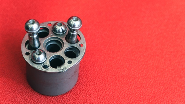
The necessary condition for the proper operation of the piston-rotor-piston joint system is to maintain the required cleanliness of the hydraulic fluid and proper clearances. Solid particles that have entered the hydraulic fluid can get trapped in the clearance gaps and hinder the smooth interaction between the components. This can lead to an excessive increase in temperature, blockage of the components, and subsequent mechanical damage.
Failures - causes and advices
Damaged piston unit
Description
The hydraulic piston unit (pump or motor) is a displacement unit in which the pumping or hydraulically driven piston moves diagonally relative to the drive axis. In the case of a pump, the rotary motion of the driving shaft drives the pump rotor, which is connected to the pistons through a joint. Hydraulic fluid is supplied to the pump through the suction side, and then the pump pistons pressurize it into the system. In the case of a hydraulic motor, pressurized fluid is supplied to its inlet, forcing the reciprocating motion of the pistons in the rotor. This motion, through the piston joint, drives the rotary motion of the rotor.
Cause of failure
Prevention
Maintaining the required cleanliness of the hydraulic fluid, among others, through proper filtration, maintaining the appropriate temperature of the hydraulic fluid during operation, and not exceeding the permissible loads of the hydraulic system.
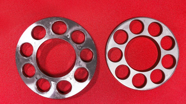
Bent shield
Description
The pump rotor rotates along with the driving shaft, carrying nine pistons. The pistons are supported by sliding shoes on the sliding surface of the swash plate and perform a reciprocating motion. The sliding shoes are pressed against the sliding surface by a backing plate called the piston shoe separator. This means that the motion is forced, i.e.
- the fluid is either being pumped when the piston, through the shoe and the swash plate, is "pushed" into the working space of the rotor.
- the fluid is being sucked in when the piston, through the shoe and the separator plate, is "pulled" out of the working space of the rotor.
Advice
A necessary condition for the proper operation of the pump is to maintain the appropriate fluid pressure in the suction part of the pump installation, as specified for each unit in the catalog sheet. This entails minimizing flow resistance and using a hydraulic fluid (such as hydraulic oil) with the correct viscosity. It is also important to keep the pressure inside the pump body below the allowable limit, which may increase over time due to internal leaks within the pump.
Prevention
- Proper design of the pump suction line, including the pipe diameter, pipe length, and suction height.
- Selecting a hydraulic fluid with the appropriate viscosity for the operating temperature of the hydraulic fluid.
- Ceasing the use of the pump when internal leaks within the pump exceed the maximum allowable value.
Breaking out bayonet plugs
Description
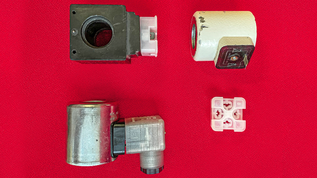
In hydraulic drive systems, electromagnets are used in control valves to regulate the direction, pressure, and flow rate, in both switching and proportional techniques. Connecting electromagnets to controllers can be done directly through electrical wires or through plug-in connections, namely plug connectors (with sockets) and pin connectors directly on the electromagnet coil.
Advice
Improper handling of pin connectors often leads to their bending and, consequently, breaking, as seen in the picture. In such cases, even though the electromagnet coil itself is functional, there is no possibility of electric current flow, resulting in the inability to control the valves. Therefore, it becomes necessary to replace the coil.
Prevention
During assembly work involving components and assemblies with electromagnets equipped with detachable plug-in connections, it is necessary to carry out the work with the special safeguards for pin connectors installed. These safeguards are provided together with new components or already mounted plug connectors.
Unit deformation
Description
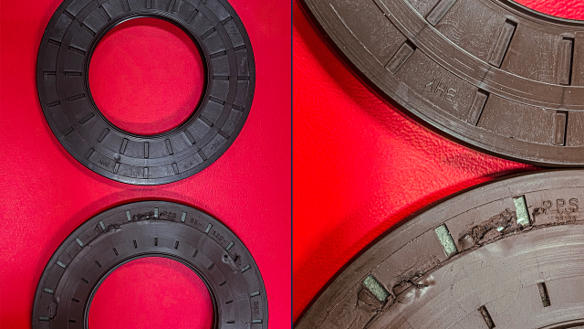
Rotary motion seals are installed on rotating or oscillating components of devices to maintain the necessary working fluid inside and ensure the long-term operation of these devices. Sealing systems must prevent leaks outside the device's housing, such as pumps, motors, or hydraulic valves. The proper functioning of such seals depends on maintaining the maximum pressure value inside the housing below the specified value in the device's datasheet. Excessive increase in the working fluid pressure inside the housing can be caused by excessive internal leaks in the hydraulic unit or excessive flow resistance in the leakage line.
Advice
In case of excessive pressure increase inside the casing of a hydraulic unit, the seals of the rotary shaft motion may become damaged or deformed. As a consequence, this leads to fluid leakage from the casing.
Prevention
- Each leakage line from individual hydraulic units must be routed separately to the reservoir and cannot be connected before reaching the reservoir.
- The selection of a working fluid with the appropriate viscosity index and viscosity at the operating temperature of the hydraulic fluid is important.
- The translation of the provided sentence is: "Ceasing the use of a hydraulic unit when leaks inside the body exceed the maximum allowable value.
Sickle insert fracture
Description
The working space of the pump is determined by the clearances between the gear teeth of both gears, compensating side plates, and the crescent insert, each of which is pressed against a gear - one with teeth facing inward, the other with teeth facing outward.
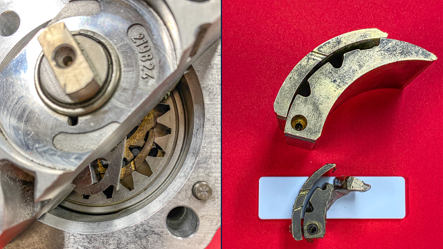
Advice
Due to the crescent insert being suspended on the shaft, the rotational movement of both gears can only have one direction - the gears slide on each part of the inserts. When attempting to rotate in the opposite direction, the outer gear can get stuck on the "edge" of the inner part of the crescent insert. The damaged component - the inner part of the crescent insert is shown in the photo. Next to it is the insert assembled in the pump. This results in the breaking of this part and the blocking of the rotational movement of the pump shaft, leading to further consequences. Ultimately, the damages to the pump make its repair uneconomical or even impossible. Prevention is crucial.
Prevention
Before the mechanical connection of the pump shaft with the drive motor shaft, it is necessary to check the compatibility of the rotational direction of both shafts. It is also important to remember the other requirements regarding the connection of pumps with drive motors specified in the product data sheets.

